Peter coppola
Junior Member
- Joined
- Aug 22, 2020
- Posts
- 20
- Reaction score
- 25
- Location
- New Jersey
- First Name
- Peter
- Truck Year
- 1979
- Truck Model
- C10
- Engine Size
- 250 I6
OK, replies to above posts 12, 13, 14 + 15.
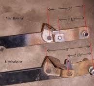
12 + 14 - The AC Delco Master Cylinder has a dimple, (not a hole with spacer) and the Cardone Booster has a solid rod with no adjustment. I was aware of the rod clearance issue when I assembled the system and a "visual" to me looked like they were close. I ordered a cheap rod check tool on Amazon ($12.00) tonight and should have it Tuesday. I do not expect it to be off, but better to check and know then ass-sume and be wrong. I will advise.
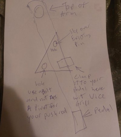
The original truck was manual brake but I changed every single part over to power brake and the ONLY part I am reusing is the clutch/brake pedals because my truck is a stick. I am using the pedal to booster rod from a power brake automatic truck that I parted out. There is no option to move the rod location on the brake pedal. The booster rod pins to the clutch pedal. Every part/line is new in the system. No old parts in the system. Even all new hardware in the drum brakes.
I doubt it is a mechanical issue in the rod arrangement because when we bleed the brakes with the truck not running, when we crack the bleeders, the pedal goes to the floor with a few inches of travel as the fluid is coming out. If there was a short rod, I expect that we would not be depressing the master enough and if the rod was long, I think my problem would be brakes dragging. Will check just the same.
13 - I have put three masters in so far. The first two, I bench bled off the truck and the third, I opted to install in the truck and bench bleed with the booster through the pedal before connecting the system feed lines. I routed bleed lines into the reservoir. The AC Delco master cylinders comes with plugs but I was dubious that it would be bled properly because every master cylinder I ever bled before had rubber bleed hoses that went back to the reservoir. I was also concerned about damaging the cups. I had read that the Master Cylinder bleed process should not be done until the fluid gravity leaks through the fitting ports so that the fluid lubricated the cups when bleeding. I don't recall any of these master cylinders ever allowing fluid to gravity bleed out of the fitting after waiting several minutes.
Front calipers are installed properly with bleeders up. I don't think it is possible to install the calipers upside down as the rubber hoses would not reach. I guess someone could get creative
15. My combo valve has the straight pin and I can see how the tool you suggest would fit. But I do not understand what is the purpose to depress this pin. The pin you are suggesting to depress is part of the metering valve. It does not connect to the shuttle valve (what you call the valve spool) that actuates the Light Switch. The tool you show is the OTC ABS Brake Proportioning Valve Depressor. My truck does not have ABS.
Currently, I have the Pressure Switch bleed tool installed to prevent the shuttle valve/valve spool from moving because on pressure imbalance, the shuttle valve blocks off the leaking side which makes bleeding a side with air impossible.
The below cutaway is my exact combo valve. Pressure switch is removed and bleed tool is installed.
SUMMARY OF MY CURRENT SYMPTOMS/EXPERIENCE/HISTORY
1. I have bled several bottles of fluid through system.
2. I am getting no bubbles from any of the four corners
3. When bleeding the two front calipers, the flow is strong. When bleeding the two rear cylinders, the flow is not as strong. Passenger rear seems better than driver rear. I have power bled all four corners with 10 psi on my power bleeder gauge. I have pedal bled all four corners. I have vacuum bled all four corners. Vacuum bleeding was least effective because the damn bleeders would leak air through the threads giving false indication of getting air out. I tried teflon tape and grease, but they still allow air in when cracked so vacuum bleeding wasted a lot of fluid.
4. With truck not running, I have a rock hard pedal within 2 inches of pressing pedal. I start the truck and the pedal is mushy to the floor. I have 18" of vacuum from manifold.
5. I have installed two combo valves, no difference. Changing combo valve is PITA as it is under radiator.
6. I have installed three master cylinders, no difference
7. I have put 10 - 12 psi press on system with power bleeder, no loss of pressure
8. I have pulled 25" of vacuum on system, no loss of vacuum.
9. Under road test, the truck will stop, but not abruptly and not able to lockup.
10. Drums are adjust properly and parking brake set during bleed process.
You must be registered for see images attach


