Odd electrical runs from starter to alternator to junction block

Disclaimer: Links on this page pointing to Amazon, eBay and other sites may include affiliate code. If you click them and make a purchase, we may earn a small commission.

mattsk8

Junior Member
Joined
Jun 5, 2024
Posts
17
Reaction score
10
Location
West Michigan
First Name
Matt
Truck Year
1986
Truck Model
K20
Engine Size
350
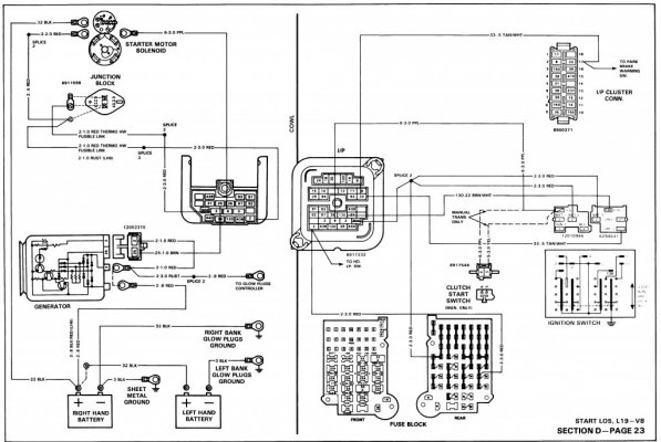
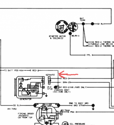
I've researched this a lot and still can't find sense to why GM wired this the way they did. On my 1986, it's wired this way...

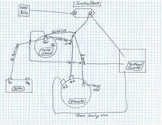
Battery to starter... Starter via fusible link, then split to 2 wires going to alternator spade 2, other wire to the bulkhead plug on the firewall... Starter via fusible link to junction block (junction block feeds HVAC relay, and another red going to the bulkhead plug)... and this is the wire that confuses me- alternator stud to junction block.

Why wouldn't GM have instead ran this charge wire to the battery stud on the starter? It would've been a shorter run. I'm asking because I'm rewiring my alternator with an 8 gauge, and I'm going to pull the wire that used to go from the alternator charge stud to the junction block out and instead go from the charge stud on the alternator to the battery terminal on the alternator. Is there any reason not to do this?? That junction already has the 12 gauge red feed from the batt terminal on the starter, I don't see why I would run the alternator charge wire all the way to that rather than going to the starter.

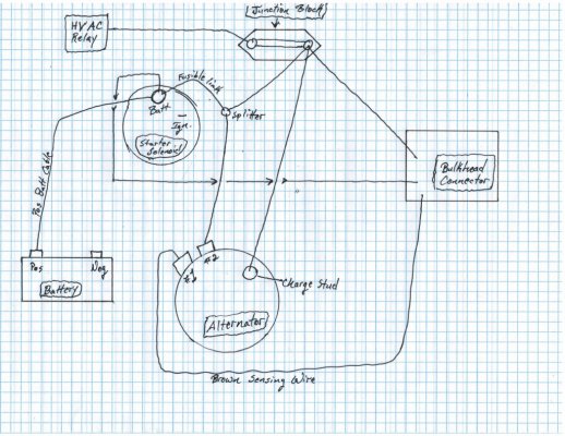
Thanks for any input and sorry if this is confusing. I can draw a picture if that would help. I have a schematic, and I've researched this a lot and haven't come up with an answer to my question. It just seems like going from the alternator charge stud straight to the batt wire on the starter (or even straight to the positive batt terminal) makes a lot more sense.
 

dsteelejr

Full Access Member
Joined
May 25, 2020
Posts
205
Reaction score
192
Location
Hudson, WY
First Name
David
Truck Year
1973, 1980
Truck Model
Cheyenne super C20 camper special, Sierra K25
Engine Size
350, 454
On its face, going from the alternator output to the junction block is convenient since you can run the wire along the valve cover and tie into the rest of the electrical system at a point where heavier gauge wires are feeding everything else.

It would seem like a pain to run the alternator output to the starter. My ‘88 K5, which is 100% stock, has a 94 amp 12si unit and has three wires that connect to the alternator output: Power feed to the firewall junction block, power feed to the to the two prong spade connector for the alternator itself, and a 8 or 10 AWG wire directly feeding the battery.

I would leave the power wire going to the junction block alone and just add a 10 AWG or heavier wire going to the positive battery with a fuse or fusible link at the battery post.

It will work without the wire going to the firewall junction block. I setup my ‘73 C20 with a 6 AWG wire and a 125 amp ANL fuse going to the battery and it works just fine, but if I did it over again I would leave the junction block wire in place to distributor the load better.
 
Last edited:

DoubleDingo

Full Access Member
Joined
Jul 3, 2012
Posts
10,640
Reaction score
15,577
Location
Right where I am
First Name
Bagoomba
Truck Year
1981
Truck Model
81-C20 Silverado Camper Special-TH400-4.10s
Engine Size
Carb'ed Vortec 350
Even though you say you have researched it, if you haven't done so, I would suggest looking up the wiring diagram for your specific vehicle. That'll tell you what that wire you're planning to change/eliminate is powering. The engineers did what they did because they are engineers and dealt with plenty of wiring scenarios over their careers.
 

mattsk8

Junior Member
Joined
Jun 5, 2024
Posts
17
Reaction score
10
Location
West Michigan
First Name
Matt
Truck Year
1986
Truck Model
K20
Engine Size
350
Even though you say you have researched it, if you haven't done so, I would suggest looking up the wiring diagram for your specific vehicle. That'll tell you what that wire you're planning to change/eliminate is powering. The engineers did what they did because they are engineers and dealt with plenty of wiring scenarios over their careers.
I have researched it a lot, not only that but I've also traced all the wires in my harness. Finding a schematic specific to a 1986 is difficult, but I've looked over the earlier schematics (which are like mine), and I've looked over the later schematics which are like @dsteelejr explained. I realize "engineers did what they did because they are engineers and dealt with plenty of wiring scenarios over their careers", but obviously they felt they could make it better because they did change the way it's wired around 1987 or 1988. Should I have stuck with the ~60 amp alternator it came with, and the original radio cuz "engineers know better"?

On its face, going from the alternator output to the junction block is convenient since you can run the wire along the valve cover and tie into the rest of the electrical system at a point where heavier gauge wires are feeding everything else.

It would seem like a pain to run the alternator output to the starter. My ‘88 K5, which is 100% stock, has a 94 amp 12si unit and has three wires that connect to the alternator output: Power feed to the firewall junction block, power feed to the to the two prong spade connector for the alternator itself, and a 8 or 10 AWG wire directly feeding the battery.

I would leave the power wire going to the junction block alone and just add a 10 AWG or heavier wire going to the positive battery with a fuse or fusible link at the battery post.

It will work without the wire going to the firewall junction block. I setup my ‘73 C20 with a 6 AWG wire and a 125 amp ANL fuse going to the battery and it works just fine, but if I did it over again I would leave the junction block wire in place to distributor the load better.
When you say you have 3 wires that connect to the alternator, are you including the brown charge wire in those 3? You have 2 wires coming off the alternator charge stud (one going to the starter and one going to the junction block on the firewall)?

My alternator has the brown sensing wire that goes from the alternator to the bulkhead connector (to the ignition). Then I have "spade 2" next to the brown wire that goes to a splitter near the starter and into a fusible link where it's connected to the battery stud on the starter and the other wire connected to that fusible link goes to the bulkhead connector. Then my charge stud on my alternator went to the junction block on the firewall. I believe these are all 12g wires.

I don't see an issue with coming off the alternator charge stud with an 8 gauge wire to the battery stud on the starter, then also running another wire from the charge stud to the junction block. I just don't understand why the charge wire needs to go from the alternator to the junction block when there is already a heavy 12v feed wire going to the junction block from the starter's batt stud.

I'm not trying to be argumentative; I'm just looking for an explanation explaining why it needs to be the way it's currently wired vs doing it the way I suggested, something besides "cuz engineers are smart".
 
Last edited:

mattsk8

Junior Member
Joined
Jun 5, 2024
Posts
17
Reaction score
10
Location
West Michigan
First Name
Matt
Truck Year
1986
Truck Model
K20
Engine Size
350
Here are the schematics I've found. Both of these show the charge wire going to the battery, and my truck did NOT have the charge wire going to the battery.

Edit: I included a third schematic, which is for my year but a 6 cylinder, but it is the way mine is wired.
 

Attachments

  • srt chrg.JPG
    srt chrg.JPG
    138 KB · Views: 15
  • Pwr Dist.JPG
    Pwr Dist.JPG
    174.9 KB · Views: 13
  • 81_87_I6_engine.jpg
    81_87_I6_engine.jpg
    76.2 KB · Views: 12
Last edited:

mattsk8

Junior Member
Joined
Jun 5, 2024
Posts
17
Reaction score
10
Location
West Michigan
First Name
Matt
Truck Year
1986
Truck Model
K20
Engine Size
350
And this is my original wiring, as well as what I'm proposing. Sorry, I'm not much of an artist lol.
 

Attachments

  • Original Wiring.jpg
    Original Wiring.jpg
    213.9 KB · Views: 13
  • New Wiring.jpg
    New Wiring.jpg
    211.9 KB · Views: 13
Last edited:

dsteelejr

Full Access Member
Joined
May 25, 2020
Posts
205
Reaction score
192
Location
Hudson, WY
First Name
David
Truck Year
1973, 1980
Truck Model
Cheyenne super C20 camper special, Sierra K25
Engine Size
350, 454
Here are the schematics I've found. Both of these show the charge wire going to the battery, and my truck did NOT have the charge wire going to the battery.

Edit: I included a third schematic, which is for my year but a 6 cylinder, but it is the way mine is wired.
I didn’t take it as being argumentative. It’s cool.

I was looking it up too, but didn’t get a chance to reply before you posted.

That’s a 12 AWG wire going from the alternator output to the junction block on the fire wall and a 10 AWG wire from the alternator output to the battery. Putting an 8 AWG wire to the battery is even better. I just didn’t want to see you running too much amperage through too few or too small AWG wires. They could potentially get hot, melt, or even catch fire if you’re running too much current through them, which is why you want to distribute the electrical load- the 12 AWG wire to feed the truck while it’s running and the 10 AWG wire to charge the battery.

What I was saying earlier about my ‘88 K5 is that the red wire on the two wire spade connector was simply jumped to the alternator output post instead of being routed all the way the junction block. The alternator output post is going to be constantly hot with battery power at all times anyways.
 

mattsk8

Junior Member
Joined
Jun 5, 2024
Posts
17
Reaction score
10
Location
West Michigan
First Name
Matt
Truck Year
1986
Truck Model
K20
Engine Size
350
I didn’t take it as being argumentative. It’s cool.

I was looking it up too, but didn’t get a chance to reply before you posted.

That’s a 12 AWG wire going from the alternator output to the junction block on the fire wall and a 10 AWG wire from the alternator output to the battery. Putting an 8 AWG wire to the battery is even better. I just didn’t want to see you running too much amperage through too few or too small AWG wires. They could potentially get hot, melt, or even catch fire if you’re running too much current through them, which is why you want to distribute the electrical load- the 12 AWG wire to feed the truck while it’s running and the 10 AWG wire to charge the battery.

What I was saying earlier about my ‘88 K5 is that the red wire on the two wire spade connector was simply jumped to the alternator output post instead of being routed all the way the junction block. The alternator output post is going to be constantly hot with battery power at all times anyways.
The main reason I'm doing this is... Someone long before me did something because there isn't a fusible link in the charge wire that went from the alternator stud to the junction block on my truck and there should be. Plus they used a butt connector at the junction block to connect the wire coming from my alternator to the wire going to the bulkhead at one end, then a wire at the other end of the butt connector that goes to the junction. This is obviously not safe because there is no fusible link, but after looking at the wiring I started wondering if it would be better to redo the wires.

I'll try to figure out what the 12 gauge wire that goes from the junction to the bulkhead powers in the cab, do the math on the amps, and make sure my wire gauge that feeds the junction is sufficient. I'll report back...
 

dsteelejr

Full Access Member
Joined
May 25, 2020
Posts
205
Reaction score
192
Location
Hudson, WY
First Name
David
Truck Year
1973, 1980
Truck Model
Cheyenne super C20 camper special, Sierra K25
Engine Size
350, 454
The main reason I'm doing this is... Someone long before me did something because there isn't a fusible link in the charge wire that went from the alternator stud to the junction block on my truck and there should be. Plus they used a butt connector at the junction block to connect the wire coming from my alternator to the wire going to the bulkhead at one end, then a wire at the other end of the butt connector that goes to the junction. This is obviously not safe because there is no fusible link, but after looking at the wiring I started wondering if it would be better to redo the wires.

I'll try to figure out what the 12 gauge wire that goes from the junction to the bulkhead powers in the cab, do the math on the amps, and make sure my wire gauge that feeds the junction is sufficient. I'll report back...
I got into wiring three years ago and I already bought a ton of materials and tools. If you’re looking to replace just one or two wires I can make you some new wires with fusible links and connectors and mail them to you. You can either give me the wire length or I can use my squares as an exemplar for a template. The tools and materials get expensive and can be hard to justify if you’re just doing a few wires.
 

dsteelejr

Full Access Member
Joined
May 25, 2020
Posts
205
Reaction score
192
Location
Hudson, WY
First Name
David
Truck Year
1973, 1980
Truck Model
Cheyenne super C20 camper special, Sierra K25
Engine Size
350, 454
I forgot to add this to my last post. The factory wire sizes are all listed on the wiring diagrams, but here is a table I use when I’m straying from the factory.
 

Attachments

  • IMG_8878.png
    IMG_8878.png
    353.6 KB · Views: 9

Jgonick

Full Access Member
Joined
Jan 12, 2017
Posts
223
Reaction score
304
Location
West Texas
First Name
Joel
Truck Year
1985
Truck Model
K10
Engine Size
350
My understanding - looked at it quickly

Junction block feeds ignition (distributor) - junction block gets power from battery & alternator. (backup redundancy) That way if a fusible link blows from starter to junction block- junction block still gets power from alternator. or visa versa.

Wiring manual LINK

86
 

Attachments

  • Screenshot from 2024-06-17 18-00-11.png
    Screenshot from 2024-06-17 18-00-11.png
    322.2 KB · Views: 12

mattsk8

Junior Member
Joined
Jun 5, 2024
Posts
17
Reaction score
10
Location
West Michigan
First Name
Matt
Truck Year
1986
Truck Model
K20
Engine Size
350
The other reason I wanted to do this was that I upgraded to a 100 amp alternator and never changed the charge wire, and the stock wire is too small. I've also upgraded the headlights, stereo, horn, added KC lights, etc, so I wanted make sure the alternator charge wire was good. I've actually done a LOT of electrical on cars, I'm just not a fan of flying blind and after a lot of research that didn't really answer any questions I decided to post here.

Anyhow... What I ended up changing was... I took the wire that used to go "starter batt stud to spade 2 on alternator", cut that and instead routed that to the junction block. Now there are 2 (I believe 12 gauge) wires feeding that junction block that both have fusible links coming from the batt wire on the starter.

I then took my new 8 gauge charge wire (with a fusible link) and ran that from the alternator stud to the batt wire on the starter. Now the alternator charging wire is sufficient and not unnecessarily long, and I have two 12 gauge wires (both with fusible links) feeding that junction block. Spade 2 "sensing wire" just has a short wire that loops over to my charge stud. Brown "excitor wire" is the same as it was.

Thanks for any input, I'm confident this is good.

I got into wiring three years ago and I already bought a ton of materials and tools. If you’re looking to replace just one or two wires I can make you some new wires with fusible links and connectors and mail them to you. You can either give me the wire length or I can use my squares as an exemplar for a template. The tools and materials get expensive and can be hard to justify if you’re just doing a few wires.
This an awesome offer and I appreciate it a lot, thank you. Fortunately I think I have this figured out!
 
Last edited:

Jgonick

Full Access Member
Joined
Jan 12, 2017
Posts
223
Reaction score
304
Location
West Texas
First Name
Joel
Truck Year
1985
Truck Model
K10
Engine Size
350
Just to clarify. On a Si alternator Spade #1 excitor wire (Brn) - it starts the alternator running. It runs to the bulkhead then to ignition switch or dummy light. Spade #2 (red) is the sensing wire, allows voltage regulator to sense voltage to know when to turn on and off alternator. Stud is the alternator output.


On the wiring diagram the first number is wire size (in metric) example 1-BRN-25 would be 16 gauge brown wire.
 

Attachments

  • wire_size.png
    wire_size.png
    52.8 KB · Views: 9

mattsk8

Junior Member
Joined
Jun 5, 2024
Posts
17
Reaction score
10
Location
West Michigan
First Name
Matt
Truck Year
1986
Truck Model
K20
Engine Size
350
Just to clarify. On a Si alternator Spade #1 excitor wire (Brn) - it starts the alternator running. It runs to the bulkhead then to ignition switch or dummy light. Spade #2 (red) is the sensing wire, allows voltage regulator to sense voltage to know when to turn on and off alternator. Stud is the alternator output.


On the wiring diagram the first number is wire size (in metric) example 1-BRN-25 would be 16 gauge brown wire.
Thanks. I have it wired correctly, just had my terminology wrong. But I appreciate the clarification for anyone that lands here searching for answers. Also thank you for clarifying how to read the wire gauge in the schematic, that's hugely beneficial!!

(I edited my earlier response to fix my terminology)
 
Last edited:

mattsk8

Junior Member
Joined
Jun 5, 2024
Posts
17
Reaction score
10
Location
West Michigan
First Name
Matt
Truck Year
1986
Truck Model
K20
Engine Size
350
My understanding - looked at it quickly

Junction block feeds ignition (distributor) - junction block gets power from battery & alternator. (backup redundancy) That way if a fusible link blows from starter to junction block- junction block still gets power from alternator. or visa versa.

Wiring manual LINK

86
I must have either missed this post, or didn't read it fully earlier. The schematic you linked is how mine was wired, except if you look at the pic, the 10 gauge wire my arrow points to was gone on my truck. That schematic shows that additional 10 gauge wire going from the alternator charge stud straight to the battery, my charge stud only had the 12 gauge wire going to the junction block on the firewall. So before I fixed mine, for my alternator to charge my battery it had to go through the 12 gauge all the way to the junction, then all the way back to the starter, then from the starter thru the battery cable to the battery.

That's what I didn't understand, your schematic shows what I was missing and also might help explain why I thought GM did that weird (GM didn't, some dumba$$ cut that wire out at some point). Thanks for posting that. I'm good now, now it goes a short distance from the alternator charge stud to the starter via 8 gauge, then to the battery via my positive battery cable.
 

Attachments

  • Screenshot_20240618-145311_1.png
    Screenshot_20240618-145311_1.png
    386.8 KB · Views: 11

Forum statistics

Threads
42,718
Posts
921,253
Members
34,277
Latest member
EddieLizLil1987
Top