Mark80K15
Full Access Member
- Joined
- Apr 18, 2021
- Posts
- 102
- Reaction score
- 73
- Location
- Sicamous, BC
- First Name
- Mark
- Truck Year
- 1980
- Truck Model
- K15
- Engine Size
- 350
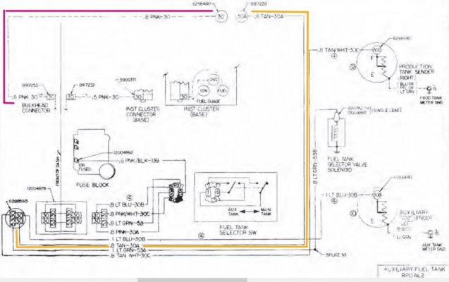
Hi, I'm using ST_352_80_1980_Chevrolet_Light_Truck_Wiring_CK_10_30_Only.pdf (don't know the actual title... the front page is not included in the PDF). Page 11 includes the "AUXILIARY FUEL TANK" schematic, and it illustrates circuits 30 and 53. Please see attached snippet "aux_fuel_tank_schematic.JPG".
These circuits support the dual fuel tank system: dashboard gauge, L/R tank switch, and sender float sensors and grounds. I have a question about circuits 30 and 30A. Circuit 30 originates at the dashboard gauge and goes to the firewall bulkhead. On my truck this wire is then routed from the firewall bulkhead (in the engine bay) over to the passenger side, and then along the frame rail to a point near the sender at the top of the passenger tank.
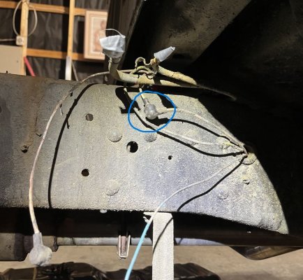
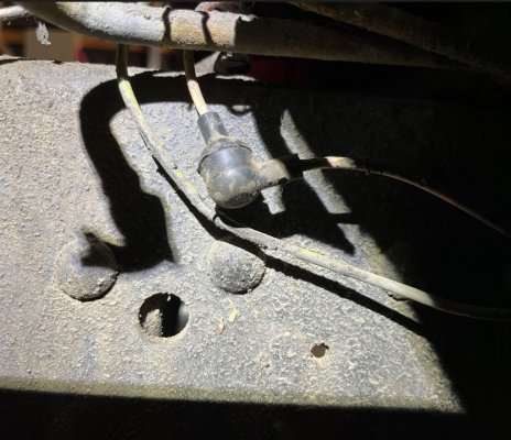
At this point there is a junction, please see attached "pic_1.JPG" and "pic_2.JPG". According to the schematic, this junction is where Circuit 30 terminates and then Circuit 30A originates. Then Circuit 30A joins with Circuits 30C (passenger side sender) and 53B (fuel tank selector), goes across a cross member to the drivers side frame rail, joins Circuit 30B (driver side sender), and finally proceeds to a plug on the firewall, and from there to the tank switch and fuse block.
Why are circuits 30 and 30A routed from the firewall bulkhead, down the frame rail all the way back to both tanks, and then all the way back to the firewall? Why does Circuit 30 terminate at that junction at the passenger tank, and why does Circuit 30A originate there? What is the purpose of that junction? Couldn't they just be one continuous wire? Does this have something to do with how GM accommodated a single tank on the passenger side versus the option of 2 tanks, with minimal rewiring?
I ask because I hate how circuits 30 and 30A are routed, and if I'm going to improve that, I'd rather take a shortcut... Route Circuit 30 directly from the firewall bulkhead to that plug on the firewall.


