Mark80K15
Full Access Member
- Joined
- Apr 18, 2021
- Posts
- 102
- Reaction score
- 72
- Location
- Sicamous, BC
- First Name
- Mark
- Truck Year
- 1980
- Truck Model
- K15
- Engine Size
- 350
Hi, thanks in advance for help. Sorry to post this but I couldn't find my particular problem.
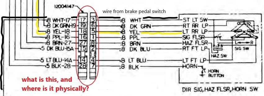
Everything works for both front and rear signal lights, all markers, signal indicator light on dash, hazards, and rear brake lights and backup lights, except for the rear signal light and brake light on the driver's side. These are powered by wire #18 Yellow as seen in the GM 1980 Wiring Diagram (ST_352_80_1980_Chevrolet_Light_Truck_Wiring_CK_10_30_Only.pdf). I unplugged the 4 prong rear light wiring harness from the bulkhead on the engine side of the firewall. Since the passenger side works, and after a bunch of testing, I tried connecting the passenger side tab from the cab (#19 Dk Green) to the #18 circuit in the harness going to the rear of the truck. The rear driver's side signal and brake lights worked fine. I also confirmed with the meter that while I was getting 12V from the #19 Dk Green tab from the cab, I was getting nothing from #18 Yellow. So I need to know why there's no power at the #18 Yellow tab from the cab when the signal is on or when the brake is depressed.
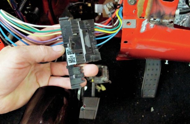
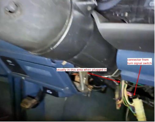
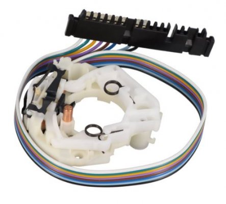
The picture I clipped and attached from the Diagram, "bulkhead_cab_side.jpg", shows the bulkhead and 4 wires exiting the firewall into the cab with #18 yellow (physically) the second plug from the top. The wire continues uninterrupted to a connector in "termination_of_18_yellow.JPG". What is that connector, and where is it physically? Is it on the steering column? Where exactly? I don't think that connector is the signal switch... I believe the signal switch is at the far right of the picture, and is inside the column near the steering wheel. I think the connector I'm asking about is near the bottom of the column and outside of it. Correct?
I also labelled the wire from the brake pedal switch, to illustrate that it goes directly to the signal switch. I think that confirms it is not part of the problem, since the signal light also fails. Yes, the signal switch could be the problem, but I should confirm if I have power at the connector I'm asking about first.


