Other than sharing a common source of vacuum to operate their respective controls, the HVAC and CC systems are entirely independent of each other. You might want to consider tackling the re-activation process one system at a time. Say you just want to re-establish the vacuum supply to the HVAC control system for now - and then at some point, want to get the CC system up and running - all you need to do is to tap into the common vacuum source. That only requires the installation of a tee and a short length of vacuum hose to the CC servo.
Connecting the HVAC controls to the vacuum source at the engine is simple enough.
The
HVAC control system has only one section of tubing (gray) that passes through the firewall and enters the engine compartment. The engine side is connected to the primary vacuum source. The source supply can be taken directly from the
intake manifold or any unported tap on the carburetor.
Whichever source you decide to use, that vacuum is applied to
port 1 on the HVAC controller valve.
Although there is only that one section of tubing that leads from the controller and passes into the engine compartment, once on the engine side it has a branch line. The branch line is connected to the main line with a tee (or Y fitting) and is lead over to the vacuum reservoir tank.
Another critical component is the check
valve. It is inserted into the main line. Be aware that it
must be located in the section of tubing that runs
between the vacuum source and the point where the line to the vacuum tank is branched off.
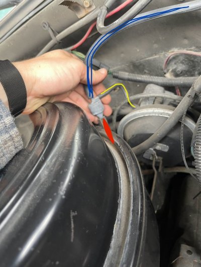
A couple of images showing what I mean. Blue is vacuum source applied to both the
controller and tank, yellow is flow in and out of the tank (explained below) and red is vacuum (from either the tank or manifold) applied to the controller:
You must be registered for see images attach
You must be registered for see images attach
Description of vacuum tank and check
valve operation - in response to a question of whether the check
valve is necessary:
If that check valve is damaged, does it absolutely have to be replaced, or can you just do a straight shot of vacuum line?
You could do that, but mode control of the HVAC would suffer during periods of low manifold vacuum (e.g. heavy loads/WOT).
The function of the check valve (and the reservoir tank) is to allow for proper operation of the mode
control even when no vacuum source is available from the engine. They work together to generate and store a supply of vacuum.
When a deep vacuum is available from the
manifold, it is used to operate the diaphragm controlled dampers. The tube that supplies
manifold vacuum to the
controls is tee'd off in the engine compartment. One side of that tee is lead over to a vacuum tank mounted on the firewall. When manifold pressure is low, a negative pressure is also developed in the vacuum tank. There's also a check valve in the section of tubing that runs from the manifold to the tee. Under ambient conditions, it is held open by a
light spring. The spring allows any negative pressure that exists in the manifold to become common with the HVAC control system. Under cruising conditions, that common negative pressure rises and falls slightly - along with any minor fluctuations in engine load/manifold pressure.
But when a heavy load is suddenly applied and the manifold pressure shoots up - the check
valve snaps shut. The seal created by the check valve isolates the two sides of the
system. On one side is the vacuum stored in the tank (along with any vacuum currently in the
control system). On the other side is the higher pressure air in the hose that is connected to the manifold. Without that check valve installed, the higher pressure air on the
manifold side of the system would be able to rush in to the
HVAC side - operating vacuum would be lost.
The volume of the tank is such that, with the check valve closed, it is able to supply the HVAC controls with sufficient vacuum for full operation. How long it can do that depends on the degree of leakage in the control tubing. But it is designed to provide operation for a reasonable amount of time.
When you let off the accelerator, the
throttle plates close down and the pressure in the
manifold starts to drop. Now, with the
throttle plates trimmed down, the pressure in the HVAC control system eventually rises above manifold pressure (or the manifold pressure drops below the HVAC pressure - whichever way you want to look at it). Either way, at some point the check valve opens. When that happens, the higher pressure air in the
control system will begin to flow towards the engine. Eventually the pressure differential between the two systems will reach equilibrium - at manifold pressure. After that, the HVAC side will kind of float along with the manifold side - until the next low engine vacuum event.
Sometimes - because the HVAC controls are operated by vacuum rather than pressure - it's difficult to visualize the direction of flow. Also, in theory there should be no net flow, just the back and forth motion of the air in the tubing. It's kind of like AC power. The only actual flow of air - through the vacuum supply hose to the
manifold - is what leaks into the
system on the HVAC side. The arrow on the check valve should point in the direction of flow; towards the intake manifold.
Vacuum schematic for HVAC controls applicable to your model year:
You must be registered for see images attach