Starter and Alternator wires

Disclaimer: Links on this page pointing to Amazon, eBay and other sites may include affiliate code. If you click them and make a purchase, we may earn a small commission.

Rooster73

Junior Member
Joined
Feb 19, 2024
Posts
12
Reaction score
12
Location
South Central Idaho
First Name
Andrew
Truck Year
1976
Truck Model
K10 Scottsdale
Engine Size
350
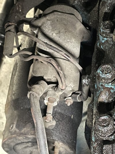
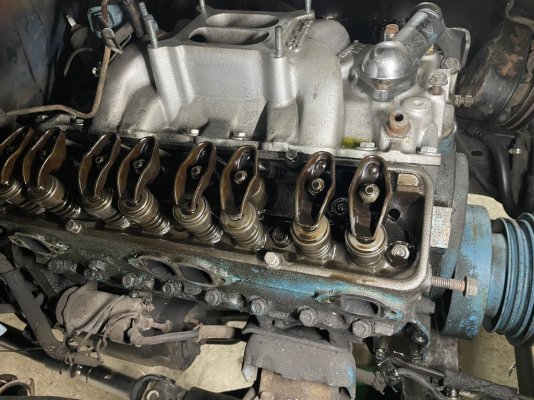
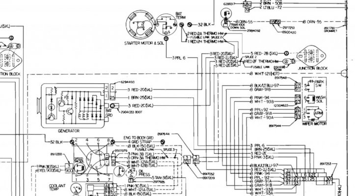
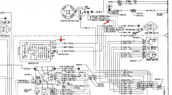
Looking for some help or at least a direction to go to find an answer. I picked up a '79 GMC k1500 Suburban. The previous owner started to pull the engine out and then gave up. The wires to the starter and to the alternator were cut. I'm not sure which wires and how many wires there should be and where they all go to and come from. I'm finding lots of wiring diagrams online, but they are confusing to me, or they conflict with each other.

Another question related... Can I solder in splices or am I going to have to pull new wires? I'm not sure if any of these wires will have fusible links and if they do, I'm not sure if they've been cut out too.

Any suggestions or direction where to find this information?

Thanks.
 

Ricko1966

Full Access Member
Joined
Apr 11, 2017
Posts
5,967
Reaction score
10,066
Location
kansas
First Name
Rick
Truck Year
1975
Truck Model
c20
Engine Size
350
Did they cut all three wires to the alternator? Starter should have two wires with fusible links going to the main post along with the positive battery cable. A purple wire going to the s terminal on the solenoid. Alternator needs 1 wire to feed 12 volts to the battery from the B+ terminal a brown wire to terminal 1 to work dash light and as exciter wire. Third wire is voltage sensing wire. Is the harness still in the truck and are the cut pieces? I can't imagine someone would cut them and disconnect them,so I'm thinking all the wires should be there. This should be a simple splice it back together situation,or splice on extensions where the harness was cut sitiation
 
Last edited:

Rooster73

Junior Member
Joined
Feb 19, 2024
Posts
12
Reaction score
12
Location
South Central Idaho
First Name
Andrew
Truck Year
1976
Truck Model
K10 Scottsdale
Engine Size
350
The cut off portions on the starter are gone. The starter was sitting inside the cab. The alternator was gone completely. I think I’ll be good to splice some sections in. I just wanted to make sure the right wires were there and I wasn’t missing any fusible links or anything. I haven’t done much rewiring so I’m not experienced with what wires exactly go where. The other square body I have the wiring is kind of cobbled so it’s not a great reference.

The harness is still in the truck. It’s almost as if they just cut the wires when removing the starter and alternator. Weird. Not how I would have thought anyone would remove the starter or alternator.
 

75gmck25

Full Access Member
Joined
Oct 13, 2016
Posts
2,382
Reaction score
2,398
Location
Northern Virginia
First Name
Bruce
Truck Year
1975
Truck Model
K25 Camper Special TH350 NP203
Engine Size
5.7
Your truck is probably wired exactly like my '75 and Rick1966's '75.
One quirk is that you may have an extra wire on the starter that runs up to the wiring loom for the in-dash ammeter (ammeter was used up through about '76). This wire has a small fuse in the harness, usually in the wiring above the passenger side valve cover.

The in-dash ammeter gauge shunt has one side connected to the full 12 volt side of the wiring at the starter, and the other side of the ammeter shunt is connected to the power junction near the brake booster. The difference in voltage between these two points is used to calculate the amps displayed on the gauge. Kind of kludgy, since an ammeter shunt needs to have a known resistance to be effective, and I'm sure the resistance of the wiring degrades over time. However, it's better than running the full amperage up and through the dash gauge.
 

mano

Junior Member
Joined
Dec 12, 2022
Posts
12
Reaction score
66
Location
Florida
First Name
mano
Truck Year
1979
Truck Model
k10
Engine Size
350
I don’t know if this will help you out or not. These pics are out of a K 10 1979. After going through four different alternators, I went with the tough stuff, one wire alternator, and haven’t had any problems since. Just ran the one wire right to the positive side of the battery.
 

Attachments

  • IMG_3156.jpeg
    IMG_3156.jpeg
    183.4 KB · Views: 22
  • IMG_3155.jpeg
    IMG_3155.jpeg
    212 KB · Views: 25

Rooster73

Junior Member
Joined
Feb 19, 2024
Posts
12
Reaction score
12
Location
South Central Idaho
First Name
Andrew
Truck Year
1976
Truck Model
K10 Scottsdale
Engine Size
350
Thank you all for the help. I’ll go take a look and see if I can make sense of it now.
 

Jgonick

Full Access Member
Joined
Jan 12, 2017
Posts
391
Reaction score
499
Location
West Texas
First Name
Joel
Truck Year
1985
Truck Model
K10
Engine Size
350
Just a FYI- On the wiring diagrams the first number (before color) is wire size in metric. The number after the color is the circuit.

Example 3 PPL 6 would be 3mm Purple 6 = 12 gauge Purple 6
 

Attachments

  • IMG_1937.jpeg
    IMG_1937.jpeg
    56 KB · Views: 21
Last edited:

spedigo

Member
Joined
Dec 6, 2023
Posts
42
Reaction score
17
Location
texas
First Name
Sam
Truck Year
1979
Truck Model
big10
Engine Size
350
Did they cut all three wires to the alternator? Starter should have two wires with fusible links going to the main post along with the positive battery cable. A purple wire going to the s terminal on the solenoid. Alternator needs 1 wire to feed 12 volts to the battery from the B+ terminal a brown wire to terminal 1 to work dash light and as exciter wire. Third wire is voltage sensing wire. Is the harness still in the truck and are the cut pieces? I can't imagine someone would cut them and disconnect them,so I'm thinking all the wires should be there. This should be a simple splice it back together situation,or splice on extensions where the harness was cut sitiation
clarification please. i’m checking all wiring from previous owner and want to be sure it’s correct and understand what options i have.

as i understand it the starter will have

1. connection to battery
2. 2 wires (that i believe both go to fuse box)
3. purple wire to S terminal that comes neutral safety switch

10 gauge or better from battery to alternator

i’ve seen some jump the voltage sensing wire to the battery connection on alternator but is this the best option? is running it to the junction block on firewall a better option?
 

Jgonick

Full Access Member
Joined
Jan 12, 2017
Posts
391
Reaction score
499
Location
West Texas
First Name
Joel
Truck Year
1985
Truck Model
K10
Engine Size
350
i’ve seen some jump the voltage sensing wire to the battery connection on alternator but is this the best option? is running it to the junction block on firewall a better option?
This is how it was explained to me-
- sensing voltage at the alternator output - seriously hamstrings the system - it's like a self-fulfilling system - it's supposed to maintain 14.0 volts, it outputs 14.0 volts, therefore everything must be OK, right? But it completely ignores voltage drop in the rest of the system - and that's bad for performance
This is where the concept of REMOTE voltage sensing comes into play. Instead of sensing system voltage at the alternator or close to it (which is like congratulating yourself on a great job regardless of the results!) - we sense system voltage where we need full voltage -. That way, when the voltage sensing circuit detects 13.0 volts at the junction block, it says: " I'm supposed to produce and output sufficient to maintain system voltage at 14.0 volts. I sense system voltage as 13.0 volts. Better increase output to 15.0 volts to bring system voltage up to 14.0 volts."

Originally it is spliced to the red wire running from starter and going to light switch. (See attachment.)

Alternatively- I've also seen it ran to the junction block.
 

Attachments

  • IMG_2181.jpg
    IMG_2181.jpg
    128.4 KB · Views: 8
Last edited:

spedigo

Member
Joined
Dec 6, 2023
Posts
42
Reaction score
17
Location
texas
First Name
Sam
Truck Year
1979
Truck Model
big10
Engine Size
350
This is how it was explained to me-
- sensing voltage at the alternator output - seriously hamstrings the system - it's like a self-fulfilling system - it's supposed to maintain 14.0 volts, it outputs 14.0 volts, therefore everything must be OK, right? But it completely ignores voltage drop in the rest of the system - and that's bad for performance
This is where the concept of REMOTE voltage sensing comes into play. Instead of sensing system voltage at the alternator or close to it (which is like congratulating yourself on a great job regardless of the results!) - we sense system voltage where we need full voltage -. That way, when the voltage sensing circuit detects 13.0 volts at the junction block, it says: " I'm supposed to produce and output sufficient to maintain system voltage at 14.0 volts. I sense system voltage as 13.0 volts. Better increase output to 15.0 volts to bring system voltage up to 14.0 volts."

Originally it is spliced to the red wire running from starter and going to light switch. (See attachment.)

Alternatively- I've also seen it ran to the junction block.
ok. makes more sense now.

so is the sensing wire from the alternator one of the two wires that are joined together on the starter post with the battery wire, correct?

If I’m remembering right (my truck is actually in a workshop out of town and it’s been a couple of weeks since I’ve been able to go out and take a look ), there are two red wires that come through the firewall, one red wire leaves the junction block and goes down to the starter. the other red wire comes from the fuse box and makes a straight run to the starter. those two join up with the battery wire and the sensing wire on the starter.

and the output wire from alternator goes to the junction block as well - in the diagram.

I know it would all make sense if I was able to just go look at my truck. But I’ve been on the road for the past couple of weeks. and my one day off a week I haven’t had a chance to go out there and sort it out. Trying to figure it all out online only has been conflicting information.
 
Last edited:

Jgonick

Full Access Member
Joined
Jan 12, 2017
Posts
391
Reaction score
499
Location
West Texas
First Name
Joel
Truck Year
1985
Truck Model
K10
Engine Size
350
so is the sensing wire from the alternator one of the two wires that are joined together on the starter post with the battery wire, correct?
Yes - originally is is spliced to a red wire (at the fusible link) that attaches to you starter with another red wire and black battery wire.

Compare the diagram above when you get to look at your truck.
 

GTX63

Full Access Member
Joined
Nov 27, 2022
Posts
994
Reaction score
4,064
Location
Tennessee
First Name
Ty
Truck Year
1985
Truck Model
K10
Engine Size
350
Seems like this guy might have what you are looking for.
xc_hide_links_from_guests_guests_error_hide_media
 

Forum statistics

Threads
44,917
Posts
971,276
Members
37,774
Latest member
twpeasley983
Top